Mastering Sequence Diagrams: A Comprehensive Guide with Visual Paradigm

Introduction
Sequence diagrams are a vital component of the Unified Modeling Language (UML), offering a dynamic view of how objects interact within a system over time. By arranging interactions chronologically along a vertical timeline, sequence diagrams illustrate the flow of messages between objects, making them an essential tool for modeling system behavior.
This guide will explore the core concepts of sequence diagrams, provide detailed examples, and offer a step-by-step tutorial for creating them using Visual Paradigm Online—a free, intuitive tool. Whether you’re capturing high-level system interactions or detailed object collaborations, this guide will equip you with the knowledge and skills to design effective sequence diagrams.
What is a Sequence Diagram?

A sequence diagram is an interaction diagram that captures how objects collaborate in a specific scenario, emphasizing the order of events. Unlike class diagrams, which focus on static structure, sequence diagrams are time-focused, using the vertical axis to represent the progression of time and horizontal lines to depict messages exchanged between objects. They are particularly useful for:
- Modeling interactions between a user and a system, between systems, or within subsystems.
- Refining use cases into detailed operational flows.
- Illustrating collaborations that realize specific operations or patterns, such as the Model-View-Controller (MVC) framework.
Sequence diagrams can vary in granularity, from high-level system sequence diagrams to detailed instance-specific interactions.
Key Concepts of Sequence Diagrams
To create meaningful sequence diagrams, you need to understand their foundational elements:
Lifeline
A lifeline represents an individual participant in the interaction, depicted as a vertical dashed line. Each lifeline is labeled with the name of an object or actor, and it extends downward to show the duration of that participant’s involvement.
Actor
An actor is an external entity—often a human user, hardware device, or another system—that interacts with the subject. Actors initiate or respond to messages but are not part of the system itself. For example, in an ATM scenario, the “Customer” is an actor.
Note:
- An actor represents a role, not a specific entity (e.g., one person can play multiple roles).
- Multiple entities can assume the same actor role.
Activation
An activation bar is a thin rectangle on a lifeline, indicating when an object is actively performing an operation. The top of the bar aligns with the start of the operation, and the bottom marks its completion.
Messages
Messages are the communications between lifelines, represented as horizontal arrows. They come in several types:
- Call Message: Invokes an operation on the target lifeline (e.g., a function call).
- Return Message: Sends information back to the caller, often shown as a dashed arrow.
- Self Message: Represents an object invoking its own operation, looping back to the same lifeline.
- Recursive Message: A self-invocation that stacks on an existing activation, indicating nested calls.
- Create Message: Instantiates a new object, typically shown with a “create” stereotype.
- Destroy Message: Requests the termination of an object’s lifecycle, marked with an “X” at the lifeline’s end.
- Duration Message: Highlights the time span of a message invocation, often shown as a slanted arrow.
Note
Notes are annotations attached to diagram elements, providing context or clarifications without affecting the model’s semantics. They are useful for explaining assumptions or constraints.
When to Use Sequence Diagrams
Sequence diagrams shine in several scenarios:
- Modeling high-level interactions between active objects or subsystems.
- Detailing how object instances collaborate to realize a use case or operation.
- Capturing generic interactions (all possible paths) or specific instances (one path).
- Visualizing frameworks like MVC, showing how model, view, and controller components interact.
Step-by-Step Guide to Creating a Sequence Diagram with Visual Paradigm
Let’s walk through the process of building a sequence diagram, using an ATM withdrawal scenario as an example.
Step 1: Identify Participants
Determine the objects and actors involved:
- Actor: Customer
- Objects: ATM Interface, ATM Controller, Bank System
Step 2: Launch Visual Paradigm Online
- Visit Visual Paradigm Online and log in (it’s free for basic use).
- Click “Create New” and select “Sequence Diagram.”
Step 3: Add Lifelines
- From the toolbar, drag the “Lifeline” icon onto the canvas for each participant (e.g., Customer, ATM Interface, ATM Controller, Bank System).
- Label each lifeline clearly.
Step 4: Define the Interaction Flow
- Start with the actor’s initial action (e.g., Customer sends “Insert Card” to ATM Interface).
- Use the “Call Message” tool to draw an arrow from Customer to ATM Interface.
- Add an activation bar on ATM Interface to show it’s processing the request.
Step 5: Add Messages
- Continue the flow:
- ATM Interface sends “Verify Card” to ATM Controller.
- ATM Controller calls “Check Card” on Bank System.
- Include return messages (e.g., Bank System returns “Card Valid” to ATM Controller).
Step 6: Handle Internal Logic
- Add a self-message if an object processes internally (e.g., ATM Controller verifies PIN).
- Use a recursive message for nested operations if needed.
Step 7: Model Object Creation/Destruction
- If a new object is instantiated (e.g., a Transaction object), use a create message.
- Mark object destruction with a destroy message if applicable.
Step 8: Add Notes and Constraints
- Attach a note to clarify assumptions (e.g., “Assumes valid PIN”).
- Use duration messages to show timing constraints if relevant.
Step 9: Refine and Export
- Adjust the layout for clarity (align lifelines, space messages evenly).
- Save your diagram and export it as PNG, PDF, or another format via the “Export” option.
Try it now: Draw your own sequence diagram with Visual Paradigm Online by clicking “Draw Now.”
Examples of Sequence Diagrams
Example 1: ATM Withdrawal
This diagram models a customer withdrawing cash:
- Participants: Customer (actor), ATM Interface, ATM Controller, Bank System.
- Flow:
- Customer → ATM Interface: “Insert Card”
- ATM Interface → ATM Controller: “Verify Card”
- ATM Controller → Bank System: “Check Card”
- Bank System → ATM Controller: “Card Valid”
- ATM Controller → ATM Interface: “Request PIN”
- Customer → ATM Interface: “Enter PIN”
- Final return: “Cash Dispensed”
Example 2: Book a Seat
This example (inspired by the original) shows a user booking a seat:
- Participants: User (actor), Interface, MainController, Routes, Route.
- Flow:
- User → Interface: “Book Seat”
- Interface → MainController: “Process Booking”
- MainController → Routes: “Get Available Routes”
- Routes → Route: “Check Availability”
- Return flow with confirmation.
Example 3: Hospital Bed Allocation
This scenario includes timing constraints:
- Participants: Nurse (actor), System, Bed Manager.
- Flow:
- Nurse → System: “Request Bed”
- System → Bed Manager: “Find Available Bed”
- Duration message shows time taken to allocate.
Tips for Effective Sequence Diagram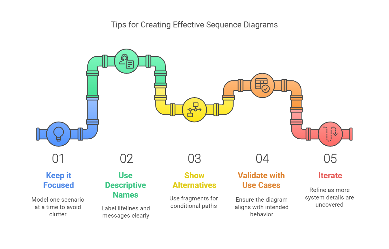
- Keep it Focused: Model one scenario at a time to avoid clutter.
- Use Descriptive Names: Label lifelines and messages clearly (e.g., “Verify Card” vs. “Message1”).
- Show Alternatives: Use fragments (e.g., “alt” for alternatives) for conditional paths.
- Validate with Use Cases: Ensure the diagram aligns with the intended behavior.
- Iterate: Refine as you uncover more details about the system.
Recommended UML Sequence Diagram
Visual Paradigm is an ideal tool for creating sequence diagrams due to several key features and benefits:
-
Comprehensive UML Support: Visual Paradigm supports all UML diagram types, including sequence diagrams. This makes it a versatile tool for modeling various aspects of a system. It provides all the necessary UML symbols and connectors to create professional-looking diagrams12.
-
User-Friendly Interface: The tool offers an intuitive and easy-to-use interface with drag-and-drop functionality. This allows users to quickly create and modify sequence diagrams without a steep learning curve. The simplicity of the interface makes it accessible for both beginners and experienced users12.
-
Time-Focused Representation: Sequence diagrams in Visual Paradigm are organized according to time, with the vertical axis representing the progression of time. This helps in visualizing the order of interactions and messages exchanged between objects, making it easier to understand the flow of operations34.
-
Advanced Visual Modeling: Visual Paradigm provides advanced visual modeling capabilities, allowing users to create complex sequence diagrams with ease. The tool supports various message types, lifelines, and interaction fragments, enabling detailed and accurate modeling of system behaviors5.
-
Collaboration Features: Visual Paradigm supports collaboration by allowing multiple users to work on the same diagram simultaneously. This feature is particularly useful for teams working on large projects, as it facilitates communication and ensures that everyone is on the same page12.
-
Integration with Other Tools: The tool integrates seamlessly with other software, such as MS Office, allowing users to embed diagrams into documents and presentations. This integration enhances the usability of the diagrams in various contexts, such as reports and meetings12.
-
Templates and Examples: Visual Paradigm offers a wide range of templates and examples for sequence diagrams, which can be used as starting points for creating new diagrams. These templates help users save time and ensure that their diagrams follow best practices12.
-
Auto-Numbering and Formatting: The tool provides features like auto-numbering of messages and customizable formatting options. These features help in maintaining the readability and organization of the diagrams, especially when dealing with complex interactions6.
-
Export and Sharing Options: Visual Paradigm allows users to export diagrams in various formats, such as PNG, JPG, PDF, and SVG. This makes it easy to share diagrams with stakeholders who may not have access to the tool12.
-
Free Version Available: Visual Paradigm offers a free community edition that supports sequence diagrams, making it accessible for users who want to learn and use UML without any cost. This version is suitable for individual users and small teams7.
Sequence Diagram Guidelines
Creating a sequence diagram involves several key guidelines to ensure clarity and accuracy. Here are the main guidelines to follow:
1. Identify Participants
- Actors: Represent users or external entities interacting with the system.
- Objects: Represent components within the system that participate in the interaction.
2. Define Messages
- Synchronous Messages: Solid lines with arrows, representing calls that wait for a response.
- Asynchronous Messages: Dashed lines with arrows, representing calls that do not wait for a response.
- Return Messages: Dashed lines with arrows, representing the return of control or data.
3. Lifelines
- Represent the existence of a participant over time.
- Use dashed lines to show the lifespan of an object.
4. Activation Bars
- Thin rectangles on lifelines indicating the duration of an operation.
- Show when an object is active or processing a message.
5. Loops, Conditions, and Alternatives
- Use frames (rectangles) to group interactions.
- Label frames with keywords like loop, alt (alternative), opt (optional), etc.
6. Notes
- Use notes to add comments or explanations.
- Attach notes to lifelines or messages using dashed lines.
7. Duration Messages
- Use notes or frames to indicate the duration of an operation or the time taken for a process.
8. Keep It Simple
- Focus on the main interactions.
- Avoid cluttering the diagram with too many details.
9. Consistency
- Use consistent naming conventions for participants and messages.
- Maintain a consistent level of abstraction.
Conclusion
Sequence diagrams are a powerful way to visualize and refine system interactions, bridging the gap between requirements and implementation. By mastering lifelines, actors, activations, and message types, you can create diagrams that communicate complex behaviors with clarity. With Visual Paradigm Online, the process becomes even more accessible—try it yourself and transform abstract scenarios into actionable designs. Whether you’re modeling an ATM, a booking system, or a hospital workflow, sequence diagrams will elevate your ability to design and collaborate effectively.
Visual Paradigm is an ideal tool for creating sequence diagrams due to its comprehensive UML support, user-friendly interface, advanced visual modeling capabilities, collaboration features, integration with other tools, templates, auto-numbering, formatting options, export and sharing options, and the availability of a free version. These features make it a powerful and versatile tool for modeling the dynamic behaviors of a system using sequence diagrams.