


Unified Modeling Language (UML) is a standardized visual modeling language designed to specify, visualize, construct, and document the artifacts of software systems. It provides a comprehensive set of diagrams and notations to represent various aspects of a system, from its structure to its behavior. UML is widely used in software development to facilitate communication among developers, stakeholders, and other team members by providing a common visual language.
Modeling tools are essential for creating and managing UML diagrams. These tools offer a range of features to support the design and documentation of software systems. They enable users to create diagrams such as Class Diagrams, Use Case Diagrams, Sequence Diagrams, and more, which help in understanding and communicating the system’s architecture and functionality.
One of the leading UML modeling tools is Visual Paradigm. It supports all UML diagram types and offers advanced features such as syntax checking, reusable elements, and the ability to establish linkages among model elements. Visual Paradigm is known for its ease of use, cross-platform compatibility, and extensive tutorials, making it an ideal choice for both individual developers and teams.
UML and modeling tools play a crucial role in software development by providing a visual and structured approach to system design and documentation. They enhance communication, improve the quality of the design, and support the development process from inception to implementation.

Key Concepts of UML Class Diagrams
-
Classes
-
A class represents a blueprint for objects in the system. It encapsulates data (attributes) and behavior (operations or methods).
-
In the example:
-
Customer,Order,OrderDetail,Item,Payment,Cash,Check, andCreditare all classes.
-
-
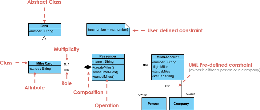
Visually, a class is depicted as a rectangle divided into three compartments:
-
Top: Class name (e.g.,
Customer). -
Middle: Attributes (e.g.,
name: String,address: String). -
Bottom: Operations (e.g.,
calcTax(),calcTotalWeight()).
-
-
-
Attributes
-
Attributes are the properties or data members of a class, often with a visibility indicator (
+for public,-for private) and a data type. -
Example: In the
Customerclass,-name: Stringand-address: Stringare private attributes.
-
-
Operations
-
Operations represent the behaviors or methods that a class can perform.
-
Example: In the
Orderclass, operations includecalcSubTotal(),calcTax(), andcalcTotalWeight().
-
-
Relationships
-
UML Class Diagrams use various relationships to show how classes interact. These include:
-
Association: A general relationship between two classes.
-
Example: The line between
CustomerandOrderindicates that a customer can place multiple orders (1 to 0..* multiplicity).
-
-
Aggregation: A “whole-part” relationship where the part can exist independently (represented by an empty diamond).
-
Example: The
Orderclass aggregatesOrderDetail(1 to 1..*).
-
-
Composition: A stronger form of aggregation where the part cannot exist without the whole (represented by a filled diamond; not shown in this example).
-
Generalization: An “is-a” relationship, showing inheritance (represented by a triangle arrow).
-
Example:
Paymentis an abstract class withCash,Check, andCreditas its subclasses.
-
-
Role: Indicates the role a class plays in a relationship (e.g.,
itemin theOrderDetailtoItemassociation).
-
-
-
Multiplicity
-
Multiplicity defines how many instances of one class can be associated with one instance of another class.
-
Example:
-
CustomertoOrderis 1 to 0..* (one customer can have zero or more orders). -
OrdertoOrderDetailis 1 to 1..* (one order can have one or more order details). -
OrderDetailtoItemis 0..* to 1 (zero or more order details can relate to one item).
-
-
-
Abstract Classes
-
An abstract class cannot be instantiated and is used as a base for other classes. It is denoted with italics or the
{abstract}keyword. -
Example:
Paymentis an abstract class withamount: floatas an attribute.
-
Guidelines for Creating UML Class Diagrams
-
Identify Classes
-
Start by identifying the main entities in your system (e.g.,
Customer,Order,Item). -
Use nouns from the problem domain to name classes.
-
-
Define Attributes and Operations
-
List the properties (attributes) and behaviors (operations) for each class.
-
Use appropriate data types and visibility modifiers (e.g.,
-for private,+for public).
-
-
Establish Relationships
-
Determine how classes relate to each other (association, aggregation, generalization).
-
Use multiplicity to specify the cardinality of relationships.
-
-
Use Abstraction
-
Identify common attributes and behaviors that can be abstracted into a superclass (e.g.,
PaymentwithCash,Check, andCreditas subclasses).
-
-
Keep It Simple
-
Avoid overloading the diagram with too many details. Focus on the most relevant classes and relationships.
-
Use packages or sub-diagrams for large systems.
-
-
Consistency
-
Follow a consistent naming convention (e.g., camelCase for attributes, PascalCase for classes).
-
Use standard UML notations to ensure clarity.
-
Tips and Tricks
-
Leverage Colors and Annotations
-
Use colors to differentiate types of classes (e.g., blue for abstract classes, green for concrete classes) or to highlight key relationships.
-
Add notes or constraints (e.g.,
{ordered}) to clarify complex relationships.
-
-
Validate with Stakeholders
-
Share the diagram with developers, designers, or clients to ensure it accurately reflects the system.
-
-
Iterate and Refine
-
Start with a high-level diagram and refine it as more details emerge. For example, the
Orderclass might initially only showdateand later includecalcTotalWeight().
-
-
Use Tools
-
Tools like Lucidchart, Visual Paradigm, or Enterprise Architect can help create and maintain UML diagrams efficiently.
-
-
Focus on Multiplicity
-
Double-check multiplicity to avoid errors. For instance, the 0..* relationship between
OrderDetailandItemsuggests an item can be part of multiple order details, which makes sense in a real-world e-commerce scenario.
-
-
Highlight Operations
-
Emphasize operations that perform calculations or critical logic (e.g.,
calcTax()inOrderDetail) to draw attention to business rules.
-
Analysis of the Class Diagram Example
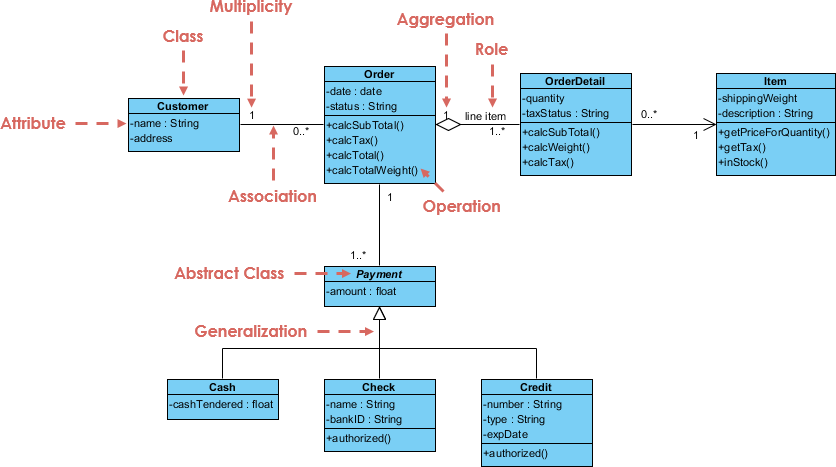
The provided UML Class Diagram represents an e-commerce order processing system. Let’s break it down:
-
Classes and Structure:
-
Customerhas attributesnameandaddressand is associated withOrder. -
OrderaggregatesOrderDetail, with attributes likedateandstatus, and operations likecalcSubTotal()andcalcTotalWeight(). -
OrderDetaillinksOrdertoItemwith attributes likequantityandtaxStatus, and operations likecalcSubTotal()andcalcTax(). -
Itemhas attributes likeshippingWeightanddescription, with operations likegetPriceForQuantity()andgetTax(). -
Paymentis an abstract class withamount, generalized intoCash,Check, andCreditwith specific attributes.
-
-
Relationships:
-
The 1 to 0..* association between
CustomerandOrderindicates a one-to-many relationship. -
The aggregation between
OrderandOrderDetail(1 to 1..*) shows that an order contains one or more details. -
The 0..* to 1 relationship between
OrderDetailandItemallows multiple order details to reference the same item. -
Generalization from
PaymenttoCash,Check, andCreditsupports polymorphism in payment processing.
-
-
Operations Insight:
-
The
calcTax()andcalcSubTotal()operations suggest a system where taxes and subtotals are computed dynamically, possibly based onquantityandtaxStatus.
-
-
Potential Improvements:
-
Add a
totalAmount: floatattribute toOrderto store the final calculated value. -
Include a bidirectional association between
OrderandPaymentto show payment linkage. -
Specify visibility for operations (e.g.,
+calcTax()or-calcTax()).
-
Recommended UML Modeling Tool
Visual Paradigm is an ideal tool for UML modeling for several reasons:
-
Comprehensive UML Support: Visual Paradigm supports all UML diagram types, including Class Diagrams, Use Case Diagrams, Sequence Diagrams, and more. This makes it a versatile tool for various modeling needs 123.
-
Ease of Use: The tool is designed to be intuitive and user-friendly, allowing users to create stunning diagrams quickly and efficiently. The Resource Catalog feature helps maximize efficiency by providing pre-built elements that can be easily incorporated into diagrams 45.
-
Cross-Platform Compatibility: Visual Paradigm can be used on any Java-enabled platform, including Windows, Mac OS X, and Linux. This flexibility ensures that users can work on their models regardless of their operating system 45.
-
Advanced Modeling Capabilities: The software offers advanced features such as syntax checking, reusable elements, and the ability to establish linkages among UML model elements and external resources. These features help ensure the correctness and consistency of the models 45.
-
Free for Personal Use: Visual Paradigm Community Edition is free for personal and non-commercial use, making it accessible to a wide range of users, including students and individual developers 45.
-
Award-Winning and Trusted: Visual Paradigm is an award-winning UML modeler, recognized for its quality and ease of use. It is trusted by over 230,000 users in companies ranging from small businesses to Fortune 500 companies, universities, and government units 165.
-
Integration and Collaboration: The tool supports team collaboration features, allowing multiple users to work on the same project. It also integrates with various development environments and tools, enhancing productivity and workflow 78.
-
Extensive Tutorials and Resources: Visual Paradigm provides a wealth of tutorials and resources to help users get started with UML modeling. These resources cover a wide range of topics and provide step-by-step instructions 8.
Conclusion
UML Class Diagrams are a powerful tool for modeling the static structure of a system. By understanding classes, attributes, operations, and relationships—along with best practices like proper multiplicity and abstraction—you can create clear and effective diagrams. The attached example demonstrates a practical application in an e-commerce context, showcasing aggregation, generalization, and operation-heavy classes. For complex systems, consider iterating on the design and using tools to maintain accuracy.
Visual Paradigm is a powerful, user-friendly, and comprehensive UML modeling tool that supports a wide range of diagrams and offers advanced features to ensure the quality and consistency of models. Its accessibility, cross-platform compatibility, and extensive resources make it an ideal choice for both individual developers and teams.
If you need more details or want me to search for additional resources, feel free to ask!